Haiku uses a custom vector image format to store icons. This is surprising both because most OSes consider bitmaps to be totally sufficient to represent icons and because there are plenty of vector graphics formats out this (e.g. SVG). The goal of the Haiku Vector Icon Format (HVIF) is to make vector icon files as small as possible. This allows Haiku to display icons as several sizes while still keeping the files small enough to fit into an inode (i.e., inside a file’s metadata). The goal of keeping the icons in the metadata is to reduce the disk reads needed to display a folder – it allows each file to only require one disk read to display.
This blog post examines the details of the HVIF format using a hex editor and the canonical parser’s source code. In the process of dissecting an example icon, I’ll also show you an optimization bug in the icon image editor.
The Problem Space: Icons
HVIF is designed especially for the icons that appear when you look at the files in a folder.. This include the files on your desktop, which is just a special folder. Each file has an icon associated with it, based on the file type. While some OSes use thumbnails for PDFs and common image types, HVIF is focused only on the symbolic, abstract icons, not on file previews.
Icons are often represented as bitmaps, and BeOS took a fairly standard approach. It had two icon sizes (16x16 and 32x32 pixels) and represented each icon as two bitmaps (one for each size). Because bitmaps are arrays of pixel colors without metadata about the “meaning” of a given pixel, resizing involves applying transformations somewhat blindly, and general creates distortions, making the image blurry or pixelated. Because there are a small, known set of sizes for icons, each size is created separately as its own image and stored separately as well.
The two bitmap files were very small – a 16x16 bitmap is 256 bytes and a 32x32 bitmap is 1024, for a total of 1280 bytes per icon. Icons have been getting bigger since the 90’s (when BeOS was developed), and modern OSes have 64x64 and 128x128 icons. Even if you only add 64x64 icons, that moves your total bytes per icon from just over 1kb to just over 5kb. Each of these jumps in size (doubling the edges) quadruples the number of pixels, and thus the storage space needed for the image.
 (image from the Icon-O-Matic documentation.)
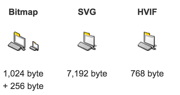
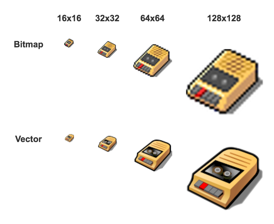
Besides bitmaps, the major option for representing images are vector formats. Haiku uses vector icons, IRIX used vector icons, even mainstream Linux desktops like Gnome and KDE can use vector icons. Vector representations work best for images that can be decomposed into lines and color gradients – which is a good fit for the abstract style common in icons. One of the big advantages of vector formats is that they’re easy to resize; because you know what the shape is supposed to be (i.e. a circle), you can render it very small or very large without distorting it. This means that you only need one file per icon; it doesn’t matter how many sizes you want to render icons at. In the image above, you can see the same icon rendered in three different file formats – bitmaps and two vector formats. The bitmaps are 16x16 and 32x32; adding a larger size there will make a big difference to the file size. The vector image file sizes will remain constant as new icon display sizes are introduced. You can see below why bitmaps need all those different files for different display sizes; when a 32x32` bitmap is blown up to larger sizes it becomes dramatically pixelated. When a vector images is scaled up, it looks just as good as at its native size. The drawback to using vector images is that it can take longer to render a vector image than a bitmap; you basically need to turn the vector image into a bitmap at the size you want to display on the screen.
 (image from the Icon-O-Matic documentation.)
The promise of vector formats for icons is that one file could be used to represent all display sizes without loss of clarity. Having one file (rather than three) could save some work for the icon artist and maybe save some file size. However, if you work with web images, you probably know that SVGs (a vector file format) aren’t always smaller than bitmap formats like PNG/JPG of the same image. Bitmaps have fairly predictable sizes based on the number of pixels in the image and the number of colors those pixels can take on. Vector images have file sizes based on the complexity of the image; it takes space to store each line/color-gradient and more space to store complex lines.
In terms of size, HVIF images compare well to BeOS’s bitmaps: real-world icons tend to be 500 to 700 bytes. You can also make ones that are under 250 bytes or a bit over 1000 bytes. This is much smaller than storing even just a 64x64 bitmap and also smaller than other vector formats (e.g., SVG). This small size is achieved by using a binary file format designed to save space (unlike SVG’s plain-text XML format). Part of the space saving design involves placing limits on the complexity of files (e.g. you can only have 256 paths).
Why do Haiku’s developers care about the size of icon files?
One kilobyte is a pretty small amount of memory on modern hard drives, or even in RAM, and it’s not like there are millions (or even tens of thousands) of icons in one operating system. They care because having especially small icon files allows an optimization that makes displaying the files in a folder faster.
If you use the standard bitmap icon formats, you’ll probably store them in their own files, separate from the files that use them. In order to display each file in a folder, the operating system will need to read the metadata for the file (including its name and file type) and then read the icon file for that file type. If the icon file were so small that you could store it in the same place as the file metadata, then you could save a read from the hard drive – you could get the metadata and the icon all in one read.
Saving one read per file doesn’t sound exciting – it’s just one. However, reading from disk is among the slowest operations: a CPU cycle can be a quarter of a nanosecond; a read from RAM is about 60 nanoseconds; a read from a relatively fast modern SSD is 20 microseconds (20,000 nanoseconds); a read from a slow disk is 10 milliseconds (10,000,000 nanoseconds). The reads from disk dominate the time it takes to display a file in a folder; it could be a significant performance gain to halve the number of disk reads even if rendering a vector image takes longer than rendering a bitmap.
Implementation Details
Because the interesting part of the file format is how small it can be, I really wanted to learn the nitty-gritty details of how it works. There’s a couple posts by Stephan Assmus, the creator of the file format, and one of them covers some key details of how the format saves space. Unfortunately, this post didn’t include enough details to satisfy my curiosity, so I used the parser’s source code and a sample HVIF file (in a hex editor) to learn more.
Example
I constructed a file in Icon-O-Matic, the application for creating/editing HVIF files. It has two shapes - a letter H on top of a blobby shape.1 The H is white and the blob has a color gradient from blue to red. The rest of the background (the 64x64 canvas) is blank/transparent. The H has been scaled up from its original size to take up most of the space.
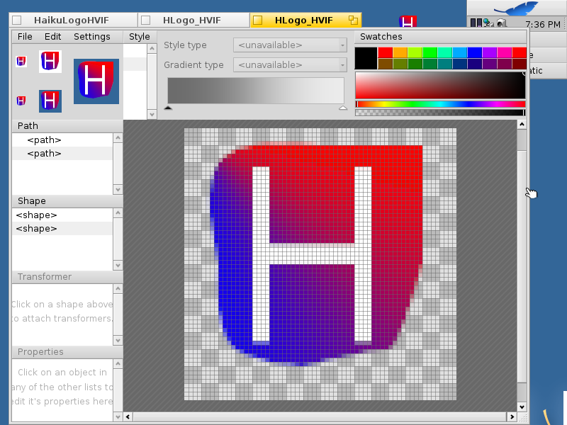
The benefit of having such a simple logo to examine is that it’s very small (128 bytes) – only 8 lines in the hex editor.
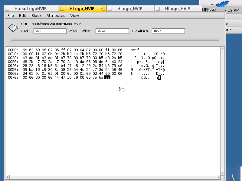
Above is Haiku’s hex editor. At the right, it the bytes interpreted as ASCII characters, with . for non-printable/invalid characters. In the middle is the bytes of the file printed as hexadecimal; each pair of characters (e.g. 6e) is one byte. Each line shows 16 bytes. On the left are character counts in hex (0x00, 0x10, 0x20, …, which would be 0, 16, 32, …, respectively in decimal) . Theses character counts act like line numbers; they’re counting the number of characters that came before that character count/line number.
Binary formats are much harder for humans to read than most plain text formats; I deciphered this file by reading the parsing code that reads these files. The file has styles, paths, and shapes, each in their own sections; shapes come last because they’re each a combination of a style and one or more paths. Here’s an overview of what all these bytes mean:
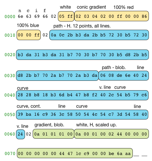
The first four bytes (6e 63 69 66) are a magic number that identifies this as an HVIF file; the letters ficn was chosen to represent ‘flat icon’. Then there are three sections (yellow, blue, green); these sections appear in every HVIF file and each one of them starts with a count of the objects in that section (all of which are 02 in this file). The yellow section is the two styles: a flat white and a red to blue gradient. The blue section is two paths: the outline of the H and the outline of the blob. The green section is two shapes; these each combine a style and a path to make the white H and colorful blob. The shape for the H also has a transformation matrix to scale it up.
Magic Number
When you’re parsing a file, it helps to be able to tell right away if it’s the type you were expecting, which is why the first four bytes are devoted to this. This is common in binary file formats. While the letters are ficn, they appear in the hex editor as ncif because the magic number is a single int32 written in little endian order, which determines the ordering of the bytes. In little-endian, the least significant byte (the n) goes first and the most significant byte (the f) goes last.
Styles
Styles are gradients and flat colors. Each shape can have one style, which is used to fill the shape with a color/gradient pattern. In order to get examples of both a color and a gradient, I made the H flat white and the blob a gradient. The first byte of this section, 02, tells us there are two styles. The first style starts right after that.
Each style will start with a style type (1 byte), which tells you how to parse the rest of that style. All of the styles include at least one color; the gradients have more colors and also have more other properties than the flat colors. HVIF represents colors as aRGB – each color has four channels: alpha (opacity), red, green, blue. Each channel takes one byte to represent (a uint8).
The first style is the flat white, represented by 05 ff. I know that the style is this long because I’ve already parsed it before explaining the file to you; otherwise, I’d have to look at the first byte (the style type, 05) and then interpret the rest from there. Objects (styles/paths/shapes) in HVIF are all variable length, to allow objects with simple or common special-case formats (like this one) to be stored very compactly. The first byte is the style type, which corresponds to an enum in the parser code. (An enum in C/C++ lets you give numeric values names; they’re often used as a way to assign different values to a related set of names – like these style types.) There are five possible style types:
STYLE_TYPE_SOLID_COLOR = 1,
STYLE_TYPE_GRADIENT = 2,
STYLE_TYPE_SOLID_COLOR_NO_ALPHA = 3,
STYLE_TYPE_SOLID_GRAY = 4,
STYLE_TYPE_SOLID_GRAY_NO_ALPHA = 5,
The flat white is STYLE_TYPE_SOLID_GRAY_NO_ALPHA. This tells us that this is: a flat color, not a gradient; a gray, meaning that the red, green, and blue channels are all equal; and completely opaque, so the alpha value will be 255. That’s a lot of information to put into one bit! Leveraging overly specific types to pack common cases into very few bits is important to keeping the files small.
Because this is a flat color, it is defined by one aRGB color. The alpha value is given by the type (NO_ALPHA). The red/green/blue value is given by the second byte: ff. All three of the color channels will be set to 255; (255, 255, 255, 255) is how aRGB represents pure white.
We’re already done with the first style. There aren’t any padding/delimiters in HVIF; that would use up space. Instead, we go straight into the second style, the gradient for the blob.
The bytes for the second style are 02 03 04 02 00 ff 00 00 86 00 00 ff. Based on the enum, 02 is STYLE_TYPE_GRADIENT; I do like that the type values are so easily human readable in the file – 2 is just 02. A gradient starts with a gradient type, gradient flags, and a gradient stop count; each of these is one byte. The gradient type here is 03, and I’ll used another enum from the parser to interpret it.
enum gradients_type {
GRADIENT_LINEAR = 0,
GRADIENT_CIRCULAR,
GRADIENT_DIAMOND,
GRADIENT_CONIC,
GRADIENT_XY,
GRADIENT_SQRT_XY
};
The enum starts at zero and increments by one with each new name, so 03 matches to the fourth name, GRADIENT_CONIC. We don’t actually need to understand this to parse the style because the gradient type affects the rendering, not the structure of the file. Every gradient has colors that start and stop at different places (i.e. starts as opaque as the aRGB color is and eventually become transparent); the gradient type determines how the renderer will fade between the colors.
The next byte, the gradient flags (04), does affect the parsing. Many HVIF objects have a flags byte near the beginning; this allows for space saving in a similar way to the various flat color types. Each bit in the flags byte has a meaning, determined by another enum:
GRADIENT_FLAG_TRANSFORM			= 1 << 1,
GRADIENT_FLAG_NO_ALPHA			= 1 << 2,
GRADIENT_FLAG_16_BIT_COLORS		= 1 << 3, // not yet used
GRADIENT_FLAG_GRAYS			= 1 << 4,
A byte has 8 bits; for 04 this is 0000 0100. The fact that there is only one bit that’s a 1 means that only one flag is set. Flags are checked using statements like gradientFlags & GRADIENT_FLAG_TRANSFORM, with a resulting value of anything greater than zero being true/the flag is set. Each flag value only has one 1 in it, so the the only one that’s set is the one whose value is 4. This means that only the GRADIENT_FLAG_NO_ALPHA is set because 1 << 2 (one left-shifted twice) is 0000 0100. This flag means that the alpha value for all the colors in the gradient is 255 (completely opaque).
You may have noticed that the flag values start at 0000 0010 and continue to 0001 0000. While not using all the bits (due to not having enough flags to need to) is fine, it seems odd to me that 0000 0001 isn’t used. I don’t have an explanation for why.
This is a gradient where the colors will not include alpha values (all are opaque), so the next step is to look at the stop count to find out how many colors there are. In this case, that’s 02, which is just 2. Each of these two colors will be 4 bytes - a stop offset plus red, green, blue. The bytes for the first color are 00 ff 00 00, which means that the stop offset is zero and the color is 100% red. The second color is 86 00 00 ff – a stop offset of 86 and 100% blue. This the end of this gradient, and (since we’ve parsed two styles) the end of the styles section.
Paths
The paths section is:
02 0a 0c 2b b3 da 2b b5 72 30 b5 72 30 b3 da 31
b3 da 31 b7 70 30 b7 70 30 b5 d8 2b b5 d8 2b b7
70 2a b7 70 2a b3 da 06 08 de 6e 40 24 28 28 b8
18 b3 6d b4 47 b8 f2 40 2c 54 b5 79 c6 39 ba 16
c9 36 3c 58 50 54 4c 54 c7 3d 54 58 40 24A path is made of line segments; each segment can be straight or curved. The H path is entirely straight lines, but the blob-path has a mix of straight lines and curves. This lets me show you two different ways paths are encoded. These differences offer space savings, like the other complexity-increasing encoding choices.
The first byte is 02 to say that there are two paths. Each path starts with a path flags byte and a point count. For the first path, this is 0a for the flags and 0c for the point count. For the flags, we care about the pattern of bits rather than the value; 0a in hex is 0000 1010 in binary. Two of the flags are set (since there are two 1s), but I’ll need another enum to decode what those mean:
PATH_FLAG_CLOSED			= 1 << 1,
PATH_FLAG_USES_COMMANDS		= 1 << 2,
PATH_FLAG_NO_CURVES			= 1 << 3,
This flag byte works the same way as the gradient style’s flag byte: PATH_FLAG_CLOSED and PATH_FLAG_NO_CURVES are true for this path. PATH_FLAG_CLOSED is direction to the renderer – “please connect the last point to the first one with a line”. This flag does not affect parsing. PATH_FLAG_NO_CURVES means there are only straight lines in this path. As important as the flags that are set, PATH_FLAG_USES_COMMANDS being false means that this path will be encoded as a list of points (we don’t have to worry about commands yet). Because this path is only straight lines, each segment will be defined by one (x,y) point.
The point count is 0c in hex – meaning 12. The first point is 2b b3 da; this is composed of an x coordinate (2b) and a y coordinate (b3 da). Each coordinate can be 1 or 2 bytes, so each point can be 2, 3, or 4 bytes. In this first path, all the points happen to have 1 byte x’s and 2 byte y’s.
Each coordinate is encoded in a special number format designed for the HVIF format. This allows integer values in the range -32 to +95 to be represented with one byte and integer values in the range -128 to +192 to be represented with two bytes. All non-integer values are represented using two bytes, and they can be in the range -128 to +192. The first bit of the first byte of a coordinate is 0 if the coordinate takes one byte and 1 if it takes two bytes. To get the value of a one byte coordinate, interpret the byte as a uint8 and then subtract 32. To get the value of a two byte coordinate, set the first bit to 0, interpret the two bytes as a uint16, divide the result by 102, and then subtract 128.
This is the code that reads one coordinate:
// read_coord
bool
read_coord(LittleEndianBuffer& buffer, float& coord)
{
	uint8 value;
	if (!buffer.Read(value))
		return false;

	if (value & 128) {
		// high bit set, the next byte is part of the coord
		uint8 lowValue;
		if (!buffer.Read(lowValue))
			return false;
		value &= 127;
		uint16 coordValue = (value << 8) | lowValue;
		coord = (float)coordValue / 102.0 - 128.0;
	} else {
		// simple coord
		coord = (float)value - 32.0;
	}
	return true;
}
While the ranges of the one-byte integers and two-byte integers are documented elsewhere, the code seems to be the only source for how to interpret a two-byte coordinate. All coordinates are 32-bit floating point numbers in the implementation, but I don’t think that’s essential to the format.
The range on the 1-byte coordinates initially confused me: why would you have a range like -32 to +95, instead of being centered at 0? An important point to remember here is that the core range is 0-64 – the coordinates that are actually on the native 64x64 canvas. Thus, the center of that range is the natural center of the coordinate system. There are 7 bits available in one byte (8 minus the flag bit), so there’s room for 127 values. By adding 32/31 values on each side of the core 0-64 range, you end up at -32 to +95. (A quick way to check whether a range might be sized to take up a given number of bits is by adding the endpoints – i.e. +32 + +95 = 127.)
This format actually makes parsing the x/y coordinates by hand pretty easy. I’m not trying to understand every single number, just figure out what each part is for. The first bit says whether this coordinate is one or two bytes; in the hex editor, this will be a letter pair that starts with 8, 9, or a letter (A through F). When I’m reading a coordinate, I can quickly figure out if this is one or two bytes and move forward; I don’t try to determine the values of all of them because it’s not interesting or useful to me.
Here are the 12 points:
| Point # | x1 | x2 | y1 | y2 |
|---|---|---|---|---|
| 1 | 2b | b3 | da | |
| 2 | 2b | b5 | 72 | |
| 3 | 30 | b5 | 72 | |
| 4 | 30 | b3 | da | |
| 5 | 31 | b3 | da | |
| 6 | 31 | b7 | 70 | |
| 7 | 30 | b7 | 70 | |
| 8 | 30 | b5 | d8 | |
| 9 | 2b | b5 | d8 | |
| 10 | 2b | b7 | 70 | |
| 11 | 2a | b7 | 70 | |
| 12 | 2a | b3 | da |
Even without turning the bytes into decimal numbers, it’s clear that most of the line segments are vertical or horizontal. I’m not sure why Icon-O-Matic chose to store the path this way, when HVIF has a special space-saving way to store horizontal or vertical line segments. Those special line segments are stored as one coordinate only, rather than the two for a basic line segment.
Using the horizontal and vertical segment types does require changing the type of the path. While lines-only paths and curves-only paths have segments of all one time, command paths allow each segment in the path to have a different type. There are four supported segment types: line, cubic curve, horizontal line, and vertical line. Command bytes near the beginning of the path – between the point count and the first point – contain a 2-bit tag for each segment in the path. A 12-point path would need three command bytes – 2 bits per point * 12 points / 8 bits per byte = 3 bytes.
The simple lines-only path requires (12 points * 3 bytes per point =) 36 bytes to represent the points. A command path would need 3 bytes to represent the segment types, but only 6 + 7 + 7 = 20 bytes to represent the points.
| Point # | Segment Type | x1 | x2 | y1 | y2 |
|---|---|---|---|---|---|
| 1 | Line | 2b | b3 | da | |
| 2 | Vertical Line | b5 | 72 | ||
| 3 | Horizontal Line | 30 | |||
| 4 | Vertical Line | b3 | da | ||
| 5 | Horizontal Line | 31 | |||
| 6 | Vertical Line | b7 | 70 | ||
| 7 | Horizontal Line | 30 | |||
| 8 | Vertical Line | b5 | d8 | ||
| 9 | Horizontal Line | 2b | |||
| 10 | Vertical Line | b7 | 70 | ||
| 11 | Horizontal Line | 2a | |||
| 12 | Vertical Line | b3 | da | ||
| Total Bytes Used: | 6 | 0 | 7 | 7 |
Using a different path type would save (36 - 23 =) 13 bytes; while that’s not a huge difference, it seems relevant in the canonical implementation of a file format designed to save space. To make sure I’m not confused about the way a command path would be represented in the file, I’m going to edit the file to just change the representation of this one path. There’s one more thing to figure out before jumping into editing: the format of a command byte.
From looking at the command byte parsing code, commands are read right to left within a byte, judging by the parsing code:
Each pair of bits matches up to a segment type:
PATH_COMMAND_H_LINE	= 0,
PATH_COMMAND_V_LINE	= 1,
PATH_COMMAND_LINE	= 2,
PATH_COMMAND_CURVE	= 3,
So, the command bytes would be 0100 0110, 0100 0100, and 0100 0100, which is 46 44 44 in hex, assuming that the bytes are read from left to right (while the bits within a byte are read right to left).
I’ll also need to change the flags byte from 0a (no curves, closed) to 06 (commands, closed). I wanted to set it to 0e (no curves, commands, closed), but that doesn’t work due to the ordering of an if statement in the parsing code:
if (pathFlags & PATH_FLAG_NO_CURVES) {
	if (!read_path_no_curves(buffer, path, pointCount))
		error = true;
} else if (pathFlags & PATH_FLAG_USES_COMMANDS) {
	if (!read_path_with_commands(buffer, path, pointCount))
		error = true;
} else {
	if (!read_path_curves(buffer, path, pointCount))
		error = true;
}
The code for the H path changes from:
0a 0c 2b b3 da 2b b5 72 30 b5 72 30 b3 da 31 b3
da 31 b7 70 30 b7 70 30 b5 d8 2b b5 d8 2b b7 70
2a b7 70 2a b3 da
To:
06 0c 46 44 44 2b b3 da b5 72 30 b3 da 31 b7 70
30 b5 d8 2b b7 70 2a b3 da
In addition to logically representing the same path (i.e the same end points for a series of line segments), the file with this path changed also looks identical to the original icon. Using the more space-expensive way of storing this path seems like a bug in Icon-O-Matic (a minor one in this case) that I could probably fix since Icon-O-Matic is open-source (like the rest of Haiku), but let’s get back to the substance of this post – understanding the image format.
Now that you’ve seen a command path, the second path will be easy to understand. It’s a command path, and the only new feature it uses are curves. All curves in HVIF are cubic curves; each one is defined by three (x,y) points. In the parser code, these are referred to as x, y, x_in, y_in, x_out, and y_out. These six values are written in the order I just named them.
The second path is:
06 08 de 6e 40 24 28 28 b8 18 b3 6d b4 47 b8 f2
40 2c 54 b5 79 c6 39 ba 16 c9 36 3c 58 50 54 4c
54 c7 3d 54 58 40 24
The first byte (06; 0000 0110) is the flags: a closed path using commands. This time the zero on the “no curves” flag is correct; this path does have curves. The second byte (08) is the point count; there are 8 points in this path. The reason this path takes more bytes despite having 60% the number of points of the previous path is that curves take a lot of bytes (6) to represent. I never thought I’d say six bytes was a lot.
The command bytes are de 6e; the segments will match up to the commands in de (1101 1110) and then the commands in 6e (0110 1110). The commands within each byte are read right to left. This results in the following commands:
| Bits | Decimal Value | Meaning |
|---|---|---|
| 10 | 2 | line |
| 11 | 3 | curve |
| 01 | 1 | vertical line |
| 11 | 3 | curve |
| 10 | 2 | line |
| 11 | 3 | curve |
| 10 | 2 | line |
| 01 | 1 | vertical line |
Editing the first path confirmed the interpretation of the command bytes; this is important because if the ordering of commands is wrong but the types are correct, then the file will look ok, but the rendered result will be different. The number of coordinates for each segment type is set, but if they are parsed in the wrong order, the coordinates will be grouped differently.
Using this command listing results in the following understanding of the path:
| Type | X | Y | Xin | Yin | Xout | Yout |
|---|---|---|---|---|---|---|
| Line | 40 | 24 | ||||
| Curve | 28 | 28 | b8 18 | b3 6d | b4 47 | b8 f2 |
| Vertical Line | <28> | 40 | ||||
| Curve | 2c | 54 | b5 79 | c6 39 | ba 16 | c9 36 |
| Line | 3c | 58 | ||||
| Curve | 50 | 54 | 4c | 54 | c7 3d | 54 |
| Line | 58 | 40 | ||||
| Vertical Line | <58> | 24 |
The <28> and <58> in the table represent the implied values for the vertical line segments; being a vertical line means copying the x of the previous point. This path is a weird mix of types since I drew it by hand, with the goal of getting as many line segment types as I could. The final path is horizontal; the shape being closed means that the final point (58, 24) is connected to the first point (40, 24) by a line segment. I intentionally made that segment horizontal, not realizing that it wouldn’t appear as a horizontal line segment in the file.
Shapes
The shapes section tells you what the renderer will actually draw. Each shape has a style and one or more paths. The space inside the path (or between the paths) will be filled with the style. The shapes are ordered back to front, so the first shape you parse will be the bottom-most layer of the image. In the logo I’m dissecting, this means the blob-shape will be first and then H-shape will be second.
The shapes section starts with a shape count – 02 because there are two shapes – and then jumps straight into the first shape. The bytes for this one are 0a 01 01 01 00 – pretty small compared to those paths.
There is only one type of shape, so both shapes in this file start with 0a, the shape type for SHAPE_TYPE_PATH_SOURCE (another enum). I’m not really sure what this means, but since there’s only one shape type, it’s pretty meaningless. The next byte of a shape is the style index. The 01 here means this shape is using the second style in this file (it’s indexed from zero); that’s the red-to-blue gradient. The next two bytes (01 01) are the path count and a path index; this shape has one path and it’s the second one in the file – the blob-y one. The last byte (00) is the shape flags; none of them are set, so I’ll wait for the next shape to discuss what the flags mean, other than that setting any of them would mean we’d have more to read for this shape.
Because shapes refer to styles (and paths) by one byte, there can only be 256 each of styles and paths in a single icon/file. (256 is the number of distinct values you can fit in 8 bits.) This is probably plenty for icons, but not enough for all complex vector graphics; being specifically for icons allows HVIF to produce smaller files by placing this limitation on complexity.
The second shape takes up more bytes: 0a 00 01 00 02 44 00 00 00 00 00 00 00 00 44 47 1c c9 00 00 be 6a aa. The first section is very similar to the first shape: the only valid shape type 0a, the first style (flat white), and one path – the first one (H). That’s the first four bytes, so we’re up to the shape flags byte – 02. Each bit in the flags byte represents a different additional feature a shape could have.
SHAPE_FLAG_TRANSFORM			= 1 << 1,
SHAPE_FLAG_HINTING			= 1 << 2,
SHAPE_FLAG_LOD_SCALE			= 1 << 3,
SHAPE_FLAG_HAS_TRANSFORMERS		= 1 << 4,
SHAPE_FLAG_TRANSLATION			= 1 << 5,
Since I’m not giving a full manual on the HVIF format, just looking at one example, I’m going to skip explaining what the other flags mean. The one that’s set in 02 is SHAPE_FLAG_TRANSFORM. This mens that there will be a six-value matrix that’s used to scale/translate/skew/rotate the path. I’m not really sure, but I think the difference between this flag and SHAPE_FLAG_HAS_TRANSFORMERS is that this flag means there’s only one transformation matrix.
The rest of this shape is six numbers. The numbers in this matrix are 24-bit floats in a format created for HVIF. Icons don’t need the precision of 32-bit floats, so using a smaller format helps save a lot of space. However, I’m not sure why 24-bit floats were chosen over 16-bit floats (a more standard format). In any case, here’s the six numbers:
| Byte1 | Byte2 | Byte3 | |
|---|---|---|---|
| 1 | 44 | 00 | 00 |
| 2 | 00 | 00 | 00 |
| 3 | 00 | 00 | 00 |
| 4 | 44 | 47 | 1c |
| 5 | c9 | 00 | 00 |
| 6 | be | 6a | aa |
This is one of the only parts of the format that’s not variable length – as soon as you read that the shape flags were 02, you’d know that the next (3 bytes per float x 6 floats = ) 18 bytes are a transformation matrix.
Since only that one flag bit was set, that’s the end of this shape. This matrix scales the H path up and moves it to the center of the image. I got the H by copy-pasting text into Icon-O-Matic, but the shape wasn’t big enough for my taste initially, so I scaled it up.
Conclusion
I like playing with Haiku; after trying a number of less-popular-than-Linux operating systems, it’s the most stable and usable of the ones I tried. It’s also different enough from Linux to have an interesting point of view. This vector icon format is just one example of that.
This vector format is interesting to me because it’s a binary format (I hadn’t parsed binary files before), it’s a vector image format (which I haven’t looked at in detail before), it has a clear constraint to optimize around (which makes the reasons behind design decisions easier to guess), and it was created mostly by one person (so it should be simple enough for me to figure out). Parsing it by hand made me a lot more comfortable converting between hex and binary and thinking about bytes as a collection of bits. Editing the files to investigate how command bytes work made me feel super cool – I edited a file by hand in a hex editor AND IT STILL WORKED! That’s a power I’d previously ascribed only to wizards with a specialty in low-level programming.
I recommend digging into the details of a binary file format with an open-source parser. Having the source code to look at while interpreting the hex was invaluable; it would have been much harder to do this without the code available. Reading about the features of HVIF and then following my curiosity about how exactly those features worked was very satisfying, and I learned new skills in the process (even if knowing the details of HVIF has very limited applicability).
Acknowledgements
Thanks to Dan Luu for comments on the post and help with the “how slow is reading from disk?” calculation, David Turner for catching awkward wording and lots of spelling mistakes, Bert Muthalaly for positive comments that make me want to write more posts, and Julia Evans for finding the confusing parts. Thanks to @davecporter for catching a typo. :)
-
This is actually my second example file; the first one was too big. I had the entire word ‘Hello’, which introduces four more paths with many more segments. In the file I constructed next, I made sure to keep things to two styles and two paths, while covering as much of the feature space as I could. One style is a flat color and the other is a gradient; the colors (e.g. fully saturated blue) were chosen to be easy to check while hand parsing the hex. One path is all straight lines (H) and the other has a mix of curves and lines (to ensure it would be encoded as a command path). The reason I used letter paths is because you can paste text into Icon-O-Matic and it just automatically makes paths for you – i.e. it’s the easiest way to make paths. ↩︎